[Tutorial] Building your own DIY E-Stim Stereo Device

This is the place for all suggestions, releases and feedback regarding Milovana Hardware efforts.
User avatar
edger477
Explorer At Heart
Explorer At Heart
Posts: 677
Joined: Mon Nov 29, 2021 8:24 pm
Gender: Male
Sexual Orientation: Straight
I am a: None of the above
Location: Europe

Re: [Tutorial] Building your own DIY E-Stim Stereo Device

Post by edger477 »

Sissyminnie wrote: Fri Jul 21, 2023 12:44 am Does it sound like I have a "bad" amplifier board or maybe something else weird may be going on?
If it feels good, and strong enough, then there is no reason to be able to turn it up more, that is why we add resistors, to reduce power of the amp so we don't stim with too much reserve power that you could deliver by turning the knob by mistake.

If you have parallel resistors, their removal should give you more power without any issues on new models of amplifiers.
UFungus
Explorer
Explorer
Posts: 28
Joined: Mon Jan 17, 2022 8:13 pm

Re: [Tutorial] Building your own DIY E-Stim Stereo Device

Post by UFungus »

I built my stereo box a while ago and I'm at my 4th or 5th amp. A few of them just ended up dying on one channel or just overheating within a few minutes. A couple of them died due to my stupidity. I've always bought pretty much the same boards with the same chip except I ordered this one too but didn't know if it was appropriate. I know enough about electronics to know where the pixies go but not enough to know how they dance, if you catch my drift. I'm thinking as long as the output is below 50w per channel, any amp is probably safe but I'd rather be sure :lol:

Here's the amp in question https://www.aliexpress.com/item/1005003 ... lRCu25fVV1
Image
User avatar
edger477
Explorer At Heart
Explorer At Heart
Posts: 677
Joined: Mon Nov 29, 2021 8:24 pm
Gender: Male
Sexual Orientation: Straight
I am a: None of the above
Location: Europe

Re: [Tutorial] Building your own DIY E-Stim Stereo Device

Post by edger477 »

Can't say what chip that has but looks same like most 12v amps. Can't know until you try.
UFungus
Explorer
Explorer
Posts: 28
Joined: Mon Jan 17, 2022 8:13 pm

Re: [Tutorial] Building your own DIY E-Stim Stereo Device

Post by UFungus »

It's a tda7388. The active cooling makes me think it likely runs hot and I'm gonna have temp issues but I'll report back if this thing is any better than the TPA3116s I've had. I'm guessing I won't see any difference between AB VS D class but who knows.
Ganiolin
Curious Newbie
Curious Newbie
Posts: 3
Joined: Mon Jul 10, 2023 8:41 pm

Re: [Tutorial] Building your own DIY E-Stim Stereo Device

Post by Ganiolin »

I have tried 4 amplifier of this type 2 bought on aliexpress and other two bought from amazon:
Image

The amplifier came from aliexpress they failed both 2 in one channel. They had one channel broken both.
The amplifiers came from amazon they both fails in both channels.

Anyway the one channel configuration was really nice and it worked well.

I plan to try to buy others amplifier on aliexpress (they costs 4$) and i hope to get at least one good

Do you have any reliable source of these amplifiers?

Thanks
Ganiolin
Curious Newbie
Curious Newbie
Posts: 3
Joined: Mon Jul 10, 2023 8:41 pm

Re: [Tutorial] Building your own DIY E-Stim Stereo Device

Post by Ganiolin »

In order to replace the dual channel amplifier as I written before, I've tried another amplifier this time MONO. The idea is put two mono amplifier in one box. Ive chosen this amplifier below because its output sould be around 120w and the voltage power is 12v-24v. I bought it from ebay. This amplifier did not worked as i explain below:

Image
TDA2050 Amplifier Board - Input voltage: DC or AC 5V-24V powered by USB - Output power: 5W-120W - Output impedance: 4-16ohm

The amplifiers did not worked but not because they are broken but I think that using this amplifier is wrong. I've attached the amplifier to a speaker after the amplifier and before the transformer and i've analyzed the signal with oscilloscope and all signals in both channels was fine and the speaker worked well. But for some reason (in my opinion the voltage after the transformes was low -around 40v max- , is too low) when i tried on my skin it had no effect was percived

Do you have some ideas of why these amplifier seems does not work well?
Ganiolin
Curious Newbie
Curious Newbie
Posts: 3
Joined: Mon Jul 10, 2023 8:41 pm

Re: [Tutorial] Building your own DIY E-Stim Stereo Device

Post by Ganiolin »

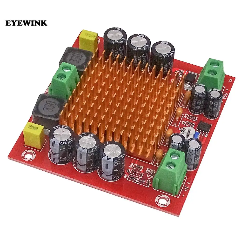
Another experiment that I want to do (and I still bought the amplifier) is to use the MONO amplifier below. This amplifier is based on the TPA3116DA same of the first two channel amplifier above listed. On aliexpress it cost around 4$ each one. i bought four with the hope to replace the two mono amplifier that i tried before.


Image
DC12V-DC26V - Max 150 W - DC12V energia 50 W, DC20V 100 W, DC24V 150 W


Do you think that this amplifier would work in this configuration?


Thanks
User avatar
DefinitelyHere
Explorer
Explorer
Posts: 9
Joined: Sun Apr 23, 2023 4:17 am

Re: [Tutorial] Building your own DIY E-Stim Stereo Device

Post by DefinitelyHere »

pvsage wrote: Mon Jul 10, 2023 1:10 pm The "Thanks Bob!" made me chuckle; until recently that was part of a meme among flerf debunkers like SciManDan. (Dan has since retired the meme after Bob Knodel's passing.)

First of all, most people seem to have best results using the 8 ohm and 0.63W taps on those 70V line transformers. I wish I could explain the reason for this in non-technical terms, but it has to do with turns ratios on the transformer and the voltage delivered at the output. Using the 8 ohm tap allows the transformer to handle more power from the amplifier, and the 0.63W tap steps the voltage up to where it will reliably cause the nerve depolarization necessary for the e-stim effect with low current. If the voltage is too low, you'll need more current to get any sensation and will have a greater risk of literally cooking your flesh.

In terms of mains electrical safety, the main concern is that there isn't a direct path between the power supply primary and secondary. If there is, mains voltage can easily find a path to ground through you and you will have a bad time.

I'd like to address the fan noise issue. If you're comfortable with soldering and have a spare 7809 lying about, try putting that between the power supply and the fan. The fan will run a little slower but should still provide more than enough airflow. The regulator will completely decouple the fan from the amplifier.
Thanks for your help, nearly done building! Quick question, so I should be using the 8ohm and 0.62W 70v (purple wire) on my specific transformers? I included screenshots of the transformer that I have. Not looking for any extreme power, and would rather play it safe. If anyone else wants to chime in, it would be greatly appreciated. Thanks!
Attachments
Screenshot_20230727_164230_Amazon Shopping.jpg
Screenshot_20230727_164230_Amazon Shopping.jpg (234.79 KiB) Viewed 6910 times
Screenshot_20230727_164655_Firefox.jpg
Screenshot_20230727_164655_Firefox.jpg (546.3 KiB) Viewed 6910 times
pvsage
Explorer
Explorer
Posts: 25
Joined: Fri Jun 16, 2023 12:22 pm

Re: [Tutorial] Building your own DIY E-Stim Stereo Device

Post by pvsage »

Sissyminnie wrote: Fri Jul 21, 2023 12:44 am Does it sound like I have a "bad" amplifier board or maybe something else weird may be going on?
How do you have the output transformers wired? For maximum energy transfer and output voltage, you should be using the highest impedance terminals on the 4/8 ohm side and the lowest current/highest impedance taps on the 70V side. If you're using 8 ohm to 0.67 A, you can get a bit more voltage at lower current (might feel stronger due to more nerve depolarization) by using the 4 ohm tap on what we're using as the primary.
pvsage
Explorer
Explorer
Posts: 25
Joined: Fri Jun 16, 2023 12:22 pm

Re: [Tutorial] Building your own DIY E-Stim Stereo Device

Post by pvsage »

DefinitelyHere wrote: Thu Jul 27, 2023 11:58 pm Thanks for your help, nearly done building! Quick question, so I should be using the 8ohm and 0.62W 70v (purple wire) on my specific transformers? I included screenshots of the transformer that I have. Not looking for any extreme power, and would rather play it safe. If anyone else wants to chime in, it would be greatly appreciated. Thanks!
Yes. 8 ohms attached in series with the resistor from the amplifier; lowest available "current" tap on the 70V side. Higher voltage at lower current will give more sensation with lower risk of physical injury.

The typical impedance for the 0.67A tap of a 70V transformer is 8000 ohms, assuming the other side is connected to a loudspeaker of the specified impedance. The effective output voltage will be pulled down by your skin, just like it is with a stun gun or taser...which is essentially what these home-built estim devices are.
pvsage
Explorer
Explorer
Posts: 25
Joined: Fri Jun 16, 2023 12:22 pm

Re: [Tutorial] Building your own DIY E-Stim Stereo Device

Post by pvsage »

Ganiolin wrote: Thu Jul 27, 2023 11:48 am I have tried 4 amplifier of this type 2 bought on aliexpress and other two bought from amazon
It seems a lot of these boards sold via Amazon, eBay, and aliexpress are rejects that couldn't be sold via the usual scumbags (that it, the more reliable suppliers). Might want to try getting one directly from a source like Parts Express.
icehash23
Explorer
Explorer
Posts: 14
Joined: Fri Nov 18, 2022 2:56 am

Re: [Tutorial] Building your own DIY E-Stim Stereo Device

Post by icehash23 »

Hi all! Veteran noob here, looking for some advice. Sorry for the wall of text.

I've been stimming on and off since I was 18 (~15 years ago). I first built a terrible mono "Davey Box" using the amp from a salvaged baby monitor (lol) with some silver solder/copper trodes. Boy, did I not know what I was missing out on! But I guess it did the trick at the time. From what I've read and experienced lately, it seems I've become pretty accustomed to the more intense stim levels...

~10 years later, I've since built two MidiStim boxes. One (back in SmartStim days, rip climberr and tronic) was a mockup using the still-OEM-packaged SASL SA-36A , with some Speco T7010 transformers (the modern revision, from B&H Photo Video). It at least served as a platform for me to know what I was getting into, and plan my design, but...

On the next build (~3 years later, ~2 years ago), I broke everything out into a very large plastic clamshell case as a sort of prototype, in order to have an easier time breadboarding and diagnosing any issues. I'm still using that amp with the adapter it came with (SAP-1238-T - 12V/3.8A, Class II double insulated).

I guess I was never really sure which tap to use, because since building this second revision, I've gravitated from Yellow (1W, used for a vast majority of my time stimming), more recently to Orange (2.5W) and upon some very recent research, way down to Purple (0.5W).

Tonight, upon switching to the Purple (8000 ohm?) tap, the start of the session seemed to be going great. I was at a comfortable stim level, but still had tons of headroom.

~1.5 hrs later, after hitting my laptop's Realtek max output + amp output volumes (while frustratingly wishing there was more) and climaxing... I began packing up, only to find that the transformers and series resistors (3.9 ohm 25W) had gotten hot enough to melt my case into my bedsheets - more severely melted was the plastic around the right channel, corresponding to my bipolar anal trode, an Estim Systems Large Flo, which always seems to take a lot more juice.

This never happened when I used the "higher" power (Orange/Yellow) taps. I've since realized (...incredibly belatedly) that since we're running these transformers "backwards", the "lower" power taps correspond to a higher voltage output, which... I guess can generate more heat?

So my guess is that the limited turn count in the "higher" power taps (yellow 1W/orange 2.5W) were the bottleneck of my rig's output, preventing any severe overheating. But after dropping "below" that (to a higher turns ratio), said bottleneck was widened, causing the overheating issues I'm seeing now.


----


tl;dr I guess my question is:

I'm encountering heat issues while capping out volumes on an SA-36A amp with Speco T7010 (8 ohm:0.5W) transformers and 3.9 ohm 25W series resistors. Apart from adding heatsinking/active cooling via metal case + fan, is there anything else I can do to increase output power overhead?

For my next build I am thinking about trying:
Any and all thoughts will be greatly appreciated! Build pics as payment :-D
User avatar
edger477
Explorer At Heart
Explorer At Heart
Posts: 677
Joined: Mon Nov 29, 2021 8:24 pm
Gender: Male
Sexual Orientation: Straight
I am a: None of the above
Location: Europe

Re: [Tutorial] Building your own DIY E-Stim Stereo Device

Post by edger477 »

icehash23 wrote: Tue Aug 01, 2023 7:19 am I'm encountering heat issues while capping out volumes on an SA-36A amp with Speco T7010 (8 ohm:0.5W) transformers and 3.9 ohm 25W series resistors. Apart from adding heatsinking/active cooling via metal case + fan, is there anything else I can do to increase output power overhead?
If tranformer has 4 ohm primary, try using that for input, but your issue comes from using the amp on max volume/power. Most of that power was converted to heat in resistor and transformer and not delivered to electrodes. If you say that purple is 8000 Ohm, that is about 10x more than human body (and for internal electrode resistance is probably below 500 Ohm). So more than 90% of that power was converted into heat inside windings (since most of resistance was there).

To reduce that, you need to use more powerful output tap. The least powerful output tap will give the most voltage/the least current, but it also has the highest internal resistance and it will produce least power when using internal electrode. We use least powerful output mainly for safety reasons (the least current will be there), but since you ran into "lack of power" issue, try using next one. You get less voltage when no load, but when connected to electrode you will get more voltage than on weakest tap, since there is less wire and internal resistance in higher power tap, so the current output will be higher. Lower internal resistance means less heat, but the main reduction in heat will be from reducing amp volume (and therefore overall power delivered to transformer).

On my transformers I am mostly using taps that have around 200-500 Ohms.
diglet
Explorer At Heart
Explorer At Heart
Posts: 204
Joined: Sun Dec 11, 2022 5:43 pm

Re: [Tutorial] Building your own DIY E-Stim Stereo Device

Post by diglet »

Ganiolin wrote: Thu Jul 27, 2023 11:48 am I have tried 4 amplifier of this type 2 bought on aliexpress and other two bought from amazon:
...
I ordered three from this seller: https://www.aliexpress.com/item/1005002780447560.html, with a few months in between orders, they all work fine even though the chip is not a real TPA3116.

Someone on discord ordered a few from amazon, they were all crap and needed big modifications to work.
pvsage
Explorer
Explorer
Posts: 25
Joined: Fri Jun 16, 2023 12:22 pm

Re: [Tutorial] Building your own DIY E-Stim Stereo Device

Post by pvsage »

icehash23 wrote: Tue Aug 01, 2023 7:19 am I'm encountering heat issues while capping out volumes on an SA-36A amp with Speco T7010 (8 ohm:0.5W) transformers and 3.9 ohm 25W series resistors. Apart from adding heatsinking/active cooling via metal case + fan, is there anything else I can do to increase output power overhead?
Try doubling up the resistors in parallel for an effective resistance of 2 ohms in series with each transformer. More of the output voltage will be dropped across the transformer, so the resistors will dissipate less power, and it will be spread out over two resistor bodies per channel.
Post Reply

Who is online

Users browsing this forum: stonecutter and 12 guests