im looking to build this device too. mainly after i found out lolol2's version, most parts are inaccessible to American shipping
ive been wondering though. apart from the basic circuit picture, is there a more "fleshed out" guide or anything that id need to know?
Low-cost (~$40-60) DIY Stereo E-stim for Audio Input (based on TroniC's MidiStim)
-
Mistypanda22

- Explorer At Heart

- Posts: 408
- Joined: Sat Mar 06, 2021 10:01 pm
- Gender: Male
- Sexual Orientation: Straight
- I am a: Submissive
Re: Low-cost (~$40-60) DIY Stereo E-stim for Audio Input (based on TroniC's MidiStim)
please help me cum v2
woooooooo! birthday on 2/18!
woooooooo! birthday on 2/18!
-
Mistypanda22
- Explorer At Heart
- Posts: 408
- Joined: Sat Mar 06, 2021 10:01 pm
- Gender: Male
- Sexual Orientation: Straight
- I am a: Submissive
Re: Low-cost (~$40-60) DIY Stereo E-stim for Audio Input (based on TroniC's MidiStim)
just have a few questions on the way this is supposed to work in general, as a lot of sources kind of... don't blatantly tell people how things work, and it would come down to trial and error.
1.)
looking at this general box, there's 4 slots. i get that the left is audio input, and i assume the right is the power input
the left and right are for the electrodes that you'd put on yourself, but.... is there any specification as to how they should be placed? like if one should be above the other? does it matter? idk
2.) looking at the transformers, what is the ideal way to hook them up? on the schematics, most of yall are saying to hook the power to ground and 8 ohms, but then go and say DONT do that? which is it
3.) also looking at the transformer, where should the positive electrode go? the 70V-0.62W slot or the 25V- 0.5W slot? i keep seeing contradictions so idk what was the consensus on these. i do know negative is to ground tho
5.)most pictures I've seen don't really have connections for a person, so im not sure how one goes from the 2 leads to a single wire plug that can be used to attach conductive lassos or rings and stuff. im really ignorant on how its supposed to work
6.)what the heck is a tri-phase
7.) ive seen a few schematics that have a parallel 10 ohm or higher resistor. is that recommended? or should i stick to the basic in series 3.9 ohm resistors?
8.) ive got a number of the key things for the build, but feel like im missing something in terms of actually making it. like proper switches or the connections from the electrodes to a jack to use. what should i get on top of the base 6 items in the head post?
overall, im lacking a lot of base knowledge of estim devices and how they work, and would like to know WHERE i can learn more about how they work, how to test them, and how to play with them
1.)
looking at this general box, there's 4 slots. i get that the left is audio input, and i assume the right is the power input
the left and right are for the electrodes that you'd put on yourself, but.... is there any specification as to how they should be placed? like if one should be above the other? does it matter? idk
- Spoiler: show
2.) looking at the transformers, what is the ideal way to hook them up? on the schematics, most of yall are saying to hook the power to ground and 8 ohms, but then go and say DONT do that? which is it
3.) also looking at the transformer, where should the positive electrode go? the 70V-0.62W slot or the 25V- 0.5W slot? i keep seeing contradictions so idk what was the consensus on these. i do know negative is to ground tho
- Spoiler: show

5.)most pictures I've seen don't really have connections for a person, so im not sure how one goes from the 2 leads to a single wire plug that can be used to attach conductive lassos or rings and stuff. im really ignorant on how its supposed to work
6.)what the heck is a tri-phase
7.) ive seen a few schematics that have a parallel 10 ohm or higher resistor. is that recommended? or should i stick to the basic in series 3.9 ohm resistors?
8.) ive got a number of the key things for the build, but feel like im missing something in terms of actually making it. like proper switches or the connections from the electrodes to a jack to use. what should i get on top of the base 6 items in the head post?
overall, im lacking a lot of base knowledge of estim devices and how they work, and would like to know WHERE i can learn more about how they work, how to test them, and how to play with them
please help me cum v2
woooooooo! birthday on 2/18!
woooooooo! birthday on 2/18!
-
Storm123
- Explorer

- Posts: 5
- Joined: Sat Sep 12, 2020 11:43 am
- Gender: Male
- Sexual Orientation: Straight
- I am a: Switch
Re: Low-cost (~$40-60) DIY Stereo E-stim for Audio Input (based on TroniC's MidiStim)
Mistypanda22 wrote: ↑Fri Feb 23, 2024 3:00 am just have a few questions on the way this is supposed to work in general, as a lot of sources kind of... don't blatantly tell people how things work, and it would come down to trial and error.
1. The box pictured is using aux sockets for the outputs (indeed the two middle ones), so with them they have two connection points in each connector (one is further in than the other) so for these both wires from one transformer was wired into the aux jack.
Many also use banana plug sockets for the outputs with them you would use two sockets for each transformer as they only take one wire per socket (contrasted to the aux plug which "merges" two cables into one socket
2. This can wary a little based on the transformer you are using. (Technically we use the transformer backwards when using them for estim) But for wiring assuming the same transformer as used in the original post:
Audio negative from amplifier to the transformers "0"
Audio positive from amplifier to serial resistor, out of the resistor to transformers 8ohm
"out" from transformers "C"/"Common" to your electrode plug "Negative"
"out" from transformers "0.5 W Purple" to your electrode plug "Positive"
3. This again is dependent on the transformer you are using, with the ones from the original post you want the purple "0.5W" one. The reason this changes is that we are looking for the best turn ratio which depends on what transformer is being used :)
4. This is one i don't have a really good answer to you on, personally i test my device on my thigh using pads, before this i often use a ohm meter to quickly check for no direct shorts between anything. If anyone has a better more "proper" way to test devices i would love if you would chime in!
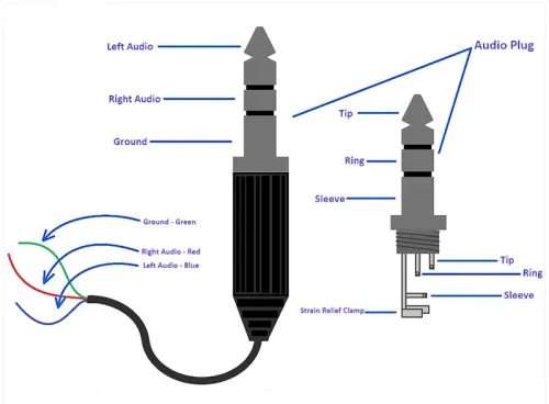
5. This again depends on what connector your using for your electrodes, if your using banana plugs or bullet plugs you already have 4 separate wires to hookup to your electrodes, in the case for something like audio plugs (aux) the split happens in the connector kinda like this image just image only two wires:
6. Thri-phase is at its core connecting the two negatives of the transformers electrode wire together, this allows us to drive 3 electrodes together that can be used to get a feeling of movement, as an example you can make the stim feel like its moving up and down. (so basically instead of having two sets of electrodes being driven entirely separately we make 3 electrodes have an output that depends on each other) Many boxes have included a switch to connect these two negative cables together at the box but you can also do this with your wires going out from your box directly, tough it can be a bit more fo a wire mess.
7. The parallel resistor, even tough many swear by it (sorry to anyone that does!) is not needed, frankly from any testing i have seen actually makes the signal slightly worse from a data standpoint. You can read a bit more about this here:
https://github.com/diglet48/restim/wiki ... l-resistor
Incase you also want to read a little about the series resistor you can find that here:
https://github.com/diglet48/restim/wiki ... s-resistor
8. Besides the basic parts you must have to make the device (Transformers, Amplifier, Power brick and plug and perhaps a box to house it in) here are a few other parts i suggest getting:
A power switch (if you want to make sure your amp does not make an unpleasant pop when being turned on or off you might want to consider a 4PST switch (its essentially a switch that flips 4 sets of switches in one, where you connect power and each electrode wire to make all of them switch on or off at once) If needed i can make a quick wiring diagram for this.
Electrode sockets - Personally i use 2mm banana sockets and 2 mm plugs on the electrode wires (If you do this you will need 4 sockets, i recommend two set of colors) so you have Transformer 1 positive to a red socket and negative to a black socket, repeat for transformer 2)
Alternatively you can also use aux sockets, they are a bit more fiddly to wire up as things a re a bit smaller, with these you would only need two, its quite popular to use these if you already have electrode wires that uses aux
A thri-phase switch, any basic on-off switch that connects the two Negative electrode wires, just makes using thri-phase a bit simpler.
As an alternative if you prefer chatting over a platform like discord for some quicker answers feel free to add me on Discord username: makeyourkink
-
Mistypanda22
- Explorer At Heart
- Posts: 408
- Joined: Sat Mar 06, 2021 10:01 pm
- Gender: Male
- Sexual Orientation: Straight
- I am a: Submissive
Re: Low-cost (~$40-60) DIY Stereo E-stim for Audio Input (based on TroniC's MidiStim)
praise the lord! i got a reply to this!
as of right now those were the main generalized questions i had while ordering the base parts
woah, i had no idea aux and banana plugs worked like that. i thought they merged all the wires into one. seems its just clumping them together to look as such the more you know
the transformer hookup, using the one recommended in the original post, seems to be hooked up the same, so that's good. and the wires being labeled is nice too. i knew that having them at different slots would give it different effects, i was just unsure if it was detrimental or it would fry the circuit, you know?
i think ill be trying to use aux plugs, as after its built, having less wires going to me is nice. I've not bought any sort of equipment that would actually be used for sessions, as i didn't know what one to get (i think i have some old electrodes that might have used aux... i think)
while i AM somewhat lightly knowledgeable about some simple circuits, I'm still too new to the whole ordeal to piece together a lot of this stuff, as they way of portraying it, as well as the attempts of people trying different methods.... it makes me just fumble around with a big head, unsure of what to do
the conversation around estim and its possibilities to hook it up just kind of confused me because of how many possible answers there were
i sent a friend request on discord, as I'm bound to have a heap load of smaller questions when i get around to building the part, but for now, thank you lots!
as of right now those were the main generalized questions i had while ordering the base parts
woah, i had no idea aux and banana plugs worked like that. i thought they merged all the wires into one. seems its just clumping them together to look as such
the transformer hookup, using the one recommended in the original post, seems to be hooked up the same, so that's good. and the wires being labeled is nice too. i knew that having them at different slots would give it different effects, i was just unsure if it was detrimental or it would fry the circuit, you know?
i think ill be trying to use aux plugs, as after its built, having less wires going to me is nice. I've not bought any sort of equipment that would actually be used for sessions, as i didn't know what one to get (i think i have some old electrodes that might have used aux... i think)
while i AM somewhat lightly knowledgeable about some simple circuits, I'm still too new to the whole ordeal to piece together a lot of this stuff, as they way of portraying it, as well as the attempts of people trying different methods.... it makes me just fumble around with a big head, unsure of what to do
the conversation around estim and its possibilities to hook it up just kind of confused me because of how many possible answers there were
i sent a friend request on discord, as I'm bound to have a heap load of smaller questions when i get around to building the part, but for now, thank you lots!
please help me cum v2
woooooooo! birthday on 2/18!
woooooooo! birthday on 2/18!
-
Spielers
- Explorer At Heart
- Posts: 302
- Joined: Mon Jan 09, 2017 8:26 pm
- Gender: Male
- Sexual Orientation: Straight
- I am a: Submissive
Re: Low-cost (~$40-60) DIY Stereo E-stim for Audio Input (based on TroniC's MidiStim)
I tryed it and for me this is really the best schematic and best feeling thanks . Note i use also a 12 V DC source (class 2!) and this ampliefier( descibed with 24V and 50W, but it works also with 12V), But i use other transformer connected with input 0Ohm and 4 Ohm and output 0W and 0,625Wramen wrote: ↑Mon Jan 24, 2022 2:30 pm I finished my box, yay! I modified a bit the original build and now it feels great.
This is my final schematic, notice the extra resistors:
The default schematic worked but felt a bit painful, with a constant "static" that got unbearable at the higher levels. After adding the two parallel resistors the static is almost gone and the signal feels very smooth, strong but not painful.
Resistors are inexpensive and this modification barely adds complexity to the build. The quality increase is MASSIVE. I highly recommend this over the original schematic (unless you like pain of course).

Who is online
Users browsing this forum: No registered users and 55 guests