Page 8 of 20

Re: FOC-Stim: a new approach to DIY stim hardware.

Posted: Thu Jan 30, 2025 6:12 am
by Bouncyboingboing
Ah. That will explain that then. Sometimes my brain is too literal. I’ve been trying to install VScode on the discovery board using STM32cube programmer. 🤣🤦‍♂️

Thanks for the tip. I hope I’ll be ok from here. We’ll see.

Cheers

Re: FOC-Stim: a new approach to DIY stim hardware.

Posted: Thu Jan 30, 2025 8:31 am
by diglet
emiumfinal wrote: Thu Jan 30, 2025 2:09 am Ok, did some more playing around and edited this for my new issue. I can get restim to connect to the board successfully on COM3, but I can't also get teleplot to show anything. If I try to connect teleplot with restim already connected I get an access denied error and vice versa (I assume because they are taking exclusive control of the port). Should I be able to connect them both to the serial port, or is teleplot getting data from restim via UDP? I have the UDP ports set up the same, but nothing seems to be working. Do I need something in the teleplot prefix field in preferences?

I'm also getting a constant error - V_BUS too low or something similar - I'm assuming that is because I haven't finished assembling the board and hooking up 12V power? Right now I am just running it with the USB connection powering the board. Just don't want to build out the board if there is some other issue I need to sort out first.
The V_BUS error means that it is waiting for you to attach the 12v power. It will not send any teleplot data until it has 12v (I should change that...).


I hope the new cable fixes DPL's issue. I was just about to say he may have a dead board :-|

Re: FOC-Stim: a new approach to DIY stim hardware.

Posted: Thu Jan 30, 2025 10:40 am
by edger477
digitalparkinglot wrote: Thu Jan 30, 2025 2:22 am After quite a bit of searching I think what my problem may be is that my micro USB cables may only be for charging and not for data. I just ordered a couple cables that support data that should be here Friday. Hopefully that fixes my problem...fingers crossed.

-digitalparkinglot
ohhh I have a drawer full of cables and was trying which ones have "long" connector that I need for my 3d printed case... and all that had long neck were charging-only :D :D

But I found these adapters that have nice connector that I need https://www.amazon.de/-/en/gp/product/B0B7RMFMN4/

Re: FOC-Stim: a new approach to DIY stim hardware.

Posted: Thu Jan 30, 2025 6:59 pm
by puste
Thanks diglet for share this super fantastic device. I have manage to get this to work.
But not without some diffeculties.

One thing I still quit undstand is the power level on this. Could you please share some more about this ?
1) Power level on the STM32 device you can change.
2) Powerlevel from script you can change.
3) And Powerlevel from the program under Volume, it says Volume ramp but seems to be in use
for this even when ramp not in use.

I have mange to create 2 different board layout on this and the first I made whas tiny, but I think it was
at bit to tiny for soldering and the 42TU200-RC I have to cut the outer legs + P S has been switch on the silk.
So I have now make a new attemt to do a second board on this. Waiting to try this out.

And the V_BUS error means I found out after try out the board. And my god it feels good.
And I will thanks all for sharing all the files to use with this device special thanks to edger477.

The reason i made them was to ensure a little les cables to connect. And for better connection.

Re: FOC-Stim: a new approach to DIY stim hardware.

Posted: Thu Jan 30, 2025 10:35 pm
by icehash23
Well I said I'd never have to build another box after my last all-out Pro Midistim build but then diglet goes and drops a whole new technology on us! 🤣 It cost about a fifth as much, too.

Put it together yesterday on some single-sided stripboard and wondered how long it'd be until someone made a PCB. Good on ya puste!

It's just in a temporary (cardboard) box for now. Took about 4 hours all told, but I was being pretty meticulous with planning and cutting jumpers, cutting strip traces neatly with a burr bit in a rotary tool, etc. Made sure it worked on the scope (200 ohm 1/4w loads was fine as a test), then went for a ride.

WOW, it's good. Seems way less "raw" than running the same pulses on my audio rig, less susceptible to electrode resistances shifting, but can still pack a punch when scripts whip around quickly. I think you don't as easily hit the "pain threshold" with it... I made it to about 70% power with the latest current maximums.

Pics:
Spoiler: show
IMG_20250130_132850.jpg
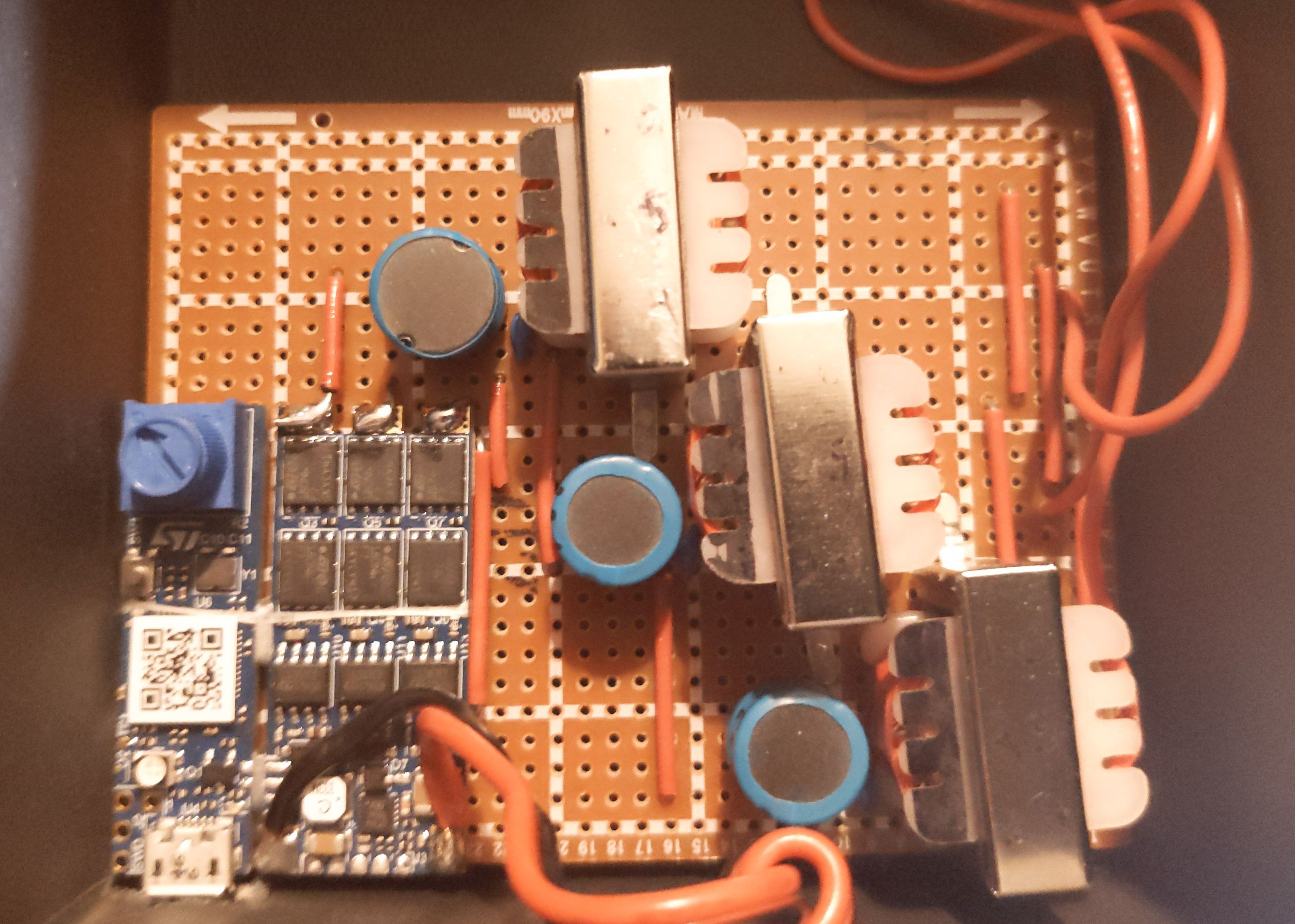
IMG_20250130_132850.jpg (763.34 KiB) Viewed 5617 times
IMG_20250130_132656.jpg
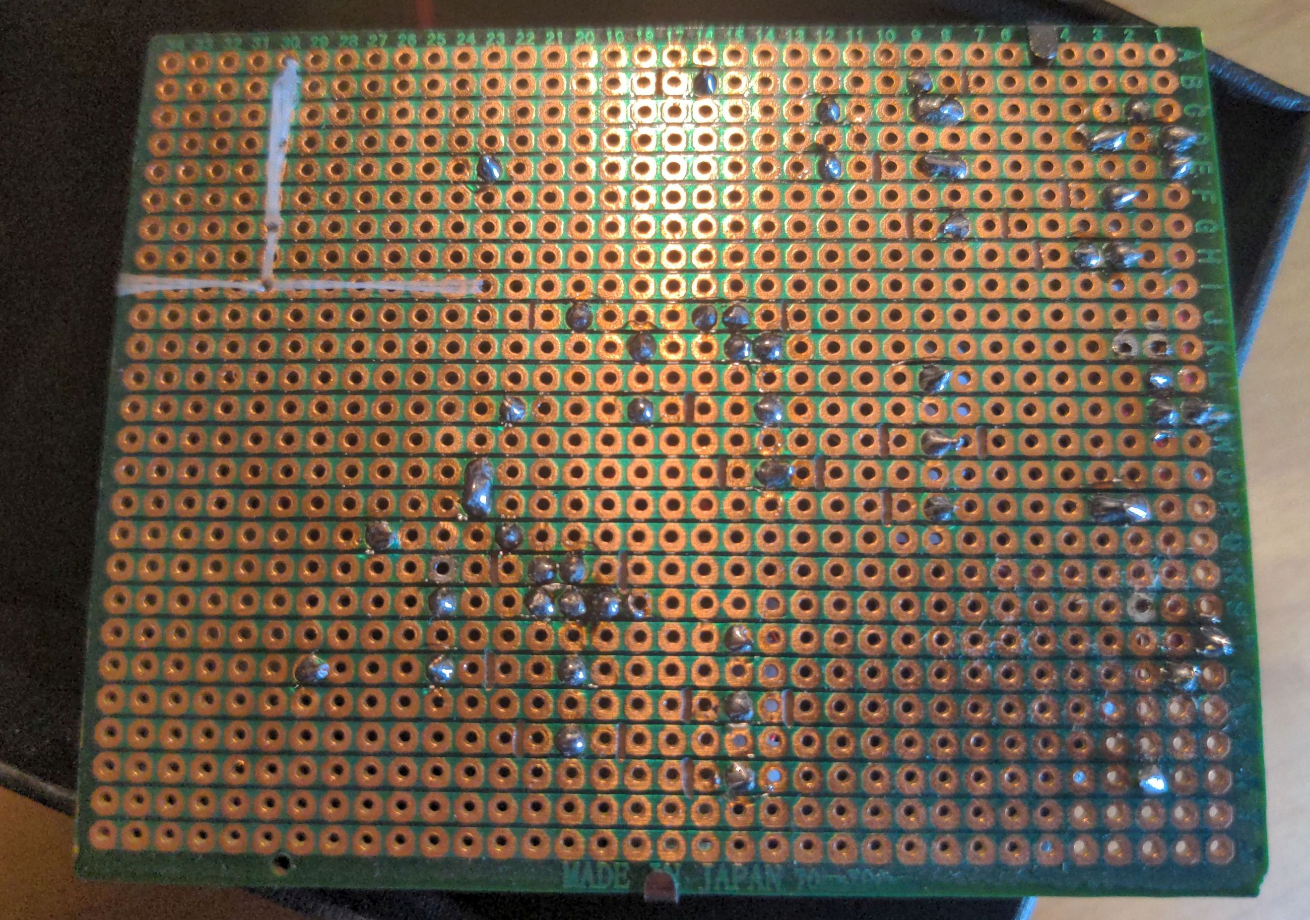
IMG_20250130_132656.jpg (857.67 KiB) Viewed 5617 times
Mounting the board definitely seems the trickiest part! I sewed it onto the stripboard in the corner with some floss around the daughterboard cutoff points, then staked it down to three separate strip rows at the outputs. The stripboard happened to fit perfectly lengthwise in this box, and the microUSB cable I chose happened to fit perfectly through the cardboard, so once connected it's in there pretty solid. Would love a 3D-printed box for it all, but somehow still haven't forked out the cash/effort for a printer. Other than that, maybe those DIN-rail-mount PCB holders could work?

For mounting the ST board to a custom PCB, I wonder about copying the through-holes by the USB Micro connector to the mainboard, then anchoring them down with headers or pieces of wire along with the outputs. Then the board is anchored with solder on two corners at least, and the USB could be run to a bigger PCB-mount jack, or a connector for a panel-mount cable. I'm a fan of the old USB-B you see on printers, but C is good space-wise. But man I wish ST had put some mounting holes on it...

Other things I'd like: A proper barrel jack instead of my dangling tail inline one of course, gotta add a volume pot, USB-C PD trigger for power maybe. I'm not jumping to add a battery but the option might be nice.

Diglet, do you know how this design could be adapted to use the "Trodes pan" section of TroniC's design? For reference:
Spoiler: show
Trodes-pan.png
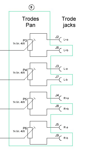
Trodes-pan.png (43.7 KiB) Viewed 5617 times
I presume just the same concept but with only 3 pots/6 jacks? I feel like I'm the only one who uses it but I love asymmetrically splitting the common between perineum/balls and anus, that's still my go-to on audio boxes. Maybe the pots could be lower-wattage now too?

I think this concept could compete with the Coyote honestly, though I don't have one to know for sure. The board is so small, even smaller when the daughterboard is removed. Paired with the right driving microcontroller, battery, BMS, protocol, open source non-spyware app? Now we're cooking with ⚡

Also sorry I missed your posts @DPL, I was thinking it could be that as I read them. Been burned by the power-only cables many times to the point where I now put a small red zip tie around them whenever I happen to find out I wasted time with them. Fingers crossed for you.

Re: FOC-Stim: a new approach to DIY stim hardware.

Posted: Thu Jan 30, 2025 11:00 pm
by diglet
puste wrote: Thu Jan 30, 2025 6:59 pm One thing I still quit undstand is the power level on this. Could you please share some more about this ?
1) Power level on the STM32 device you can change.
2) Powerlevel from script you can change.
3) And Powerlevel from the program under Volume, it says Volume ramp but seems to be in use
for this even when ramp not in use.
Thank you.

It works the same as with stereostim, all 3 volumes are multiplied together to get the final signal volume.
icehash23 wrote: Thu Jan 30, 2025 10:35 pm Diglet, do you know how this design could be adapted to use the "Trodes pan" section of TroniC's design? For reference:
I've never seen the trodes pan functionality. I assume it's a way to control more electrodes than there are outputs? The design you have shown should work, the software will learn the new circuit parameters as you pan between the electrodes :-)

There are several boxes with 4 outputs in the works, some of which use only one or even zero transformers. That should make hardware based pan functionality obsolete, eventually.

Re: FOC-Stim: a new approach to DIY stim hardware.

Posted: Fri Jan 31, 2025 12:07 am
by icehash23
diglet wrote: Thu Jan 30, 2025 11:00 pm I've never seen the trodes pan functionality. I assume it's a way to control more electrodes than there are outputs? The design you have shown should work, the software will learn the new circuit parameters as you pan between the electrodes :-)
It is, yeah. Or you can even adjust which trode is seen as the common on the fly, by jumpering, then setting pots to their limits. It doesn't fully separate, but puts 1kohm in series, which gets pretty close. Makes it a bit more modular. I've done things like using two trodes on the top/bottom of balls and the pan lets you more finely dial in sensations. It is one more knob to make sure is in the right position before calibrating, though. More variables, more fuss. I have been eyeing the Trippple from E-stim Systems, but $$$, and my setups get too complex already :lol:

I'll try to find a more permanent box and give it a go!
There are several boxes with 4 outputs in the works, some of which use only one or even zero transformers. That should make hardware based pan functionality obsolete, eventually.
How would 4 outputs work, multiple dev boards? Zero transformers still seems baffling to me, but I guess that's how the 2B and Coyote already work. I know there was a really low-profile design they were working on at smartstim before it went down. Wish I'd archived that.

Re: FOC-Stim: a new approach to DIY stim hardware.

Posted: Fri Jan 31, 2025 12:47 am
by edger477
icehash23 wrote: Fri Jan 31, 2025 12:07 am Wish I'd archived that.
I have PDF with the current pump somewhere... but I think is obsolete now... Don't need to with for that :D

Re: FOC-Stim: a new approach to DIY stim hardware.

Posted: Fri Jan 31, 2025 11:54 am
by diglet
icehash23 wrote: Fri Jan 31, 2025 12:07 am
There are several boxes with 4 outputs in the works, some of which use only one or even zero transformers. That should make hardware based pan functionality obsolete, eventually.
How would 4 outputs work, multiple dev boards? Zero transformers still seems baffling to me, but I guess that's how the 2B and Coyote already work. I know there was a really low-profile design they were working on at smartstim before it went down. Wish I'd archived that.
F12345U is working on a design based on MAX22213, a tiny 4-channel motor driver chip. This will require 4 transformers.

Onwrikbaar is working on the NeoDK, a 4-output box with 1 transformer. I'm working on Restim integration right now. https://github.com/Onwrikbaar/NeoDK

Elims is working on Noisy Cricket, a creditcard-sized transformerless output stage (design working, but github not available yet). He offered to build a 3-channel output stage for me but I told him no because I already have too many kink projects lined up for this month :weep:. Maybe in a few months if these options don't work out.

Re: FOC-Stim: a new approach to DIY stim hardware.

Posted: Fri Jan 31, 2025 10:22 pm
by icehash23
Awesome, thanks for that. I'll be checking 'em out.

@edger I don't believe any technology is ever fully obsolete, they just have pros and (sometimes prohibitively-severe) cons. And everything can be learned from!

Re: FOC-Stim: a new approach to DIY stim hardware.

Posted: Fri Jan 31, 2025 10:25 pm
by edger477
icehash23 wrote: Fri Jan 31, 2025 10:22 pm they just have pros and (sometimes prohibitively-severe) cons.
Once a new technology is available that has same pros without the cons... I'd call the old one "obsolete" :)

Re: FOC-Stim: a new approach to DIY stim hardware.

Posted: Fri Jan 31, 2025 11:28 pm
by emiumfinal
Has anyone tried removing the potentiometer from the ST board and wiring in an external one? If so, can you show how you have it wired - I'm interested in doing that, but I'm not sure which pin on the pot goes to which pin on the board.

Re: FOC-Stim: a new approach to DIY stim hardware.

Posted: Sat Feb 01, 2025 2:45 am
by icehash23
EDIT: Turns out this is partially wrong, somehow? See bottom edit note.
emiumfinal wrote: Fri Jan 31, 2025 11:28 pm Has anyone tried removing the potentiometer from the ST board and wiring in an external one? If so, can you show how you have it wired - I'm interested in doing that, but I'm not sure which pin on the pot goes to which pin on the board.
I plugged ST's Board Design project files into Altium's online viewer for you:
Spoiler: show
Screenshot_20250131_184111.png
Screenshot_20250131_184111.png (45.3 KiB) Viewed 5362 times
That's a top-down view, with USB in the bottom left.

Hope that helps. As long as you get the wiper (pin 2) right, worst that can happen is volume increasing when you turn CCW (meaning pins 1 and 3 are swapped)... which is a good reason to set software volume limits low, and not test on flesh!

Ideally use a multimeter to check which pin on your replacement pot is the wiper. Whichever pin, when checked against the wiper, shows 0 ohms when the pot is fully CCW, that's the ground. There should be 10 kOhms between two pins no matter the position of the wiper, those two pins are 1/3.

Also the pot is a Bourns 3386P-1-103TLF which is a 10 kOhm half-watt. Datasheet doesn't say so I'm assuming linear style, not logarithmic. Try to use at least a 0.5W external pot, though most chassis mount are more than that IIRC.

EDIT: emiumfinal found out that the gerber screenshot above is backwards somehow - GND and VCC are swapped, even though I pulled files straight from ST. I confirmed myself later. Good lesson in that, always measure in circuit, out of circuit, and repeat with the replacement part! Meter > CAD

Re: FOC-Stim: a new approach to DIY stim hardware.

Posted: Sat Feb 01, 2025 11:59 am
by f12345u
Here's the board I made for the B-G431-ESC1 version of FOC-Stim.
Features
  • USB-C
  • DC Jack
  • Pot
  • 4MM Banana Jacks
  • Power Switch
  • Compact
I am including a mega link to the PCB files to have it made at JLCPCB.
The only parts that I had placed by JLCPCB is the USB port and its resistors, everything else is the standard FOC-Stim BOM from the Github repo that can be sourced from either Mouser, Aliexpress or Amazon.
The enclosure for this is from Senorgif. I can ask if they want to release the files to 3d print the enclosure :-)
Final Box.jpg
Final Box.jpg (472.04 KiB) Viewed 5313 times
Completed board top.jpg
Completed board top.jpg (660 KiB) Viewed 5313 times
Completed board bottom.jpg
Completed board bottom.jpg (528.53 KiB) Viewed 5313 times
Spoiler: show
https://mega.nz/folder/fgchRJRK
Decrypt: NhsmvHoiy1tz09Er9PjgBg

Re: FOC-Stim: a new approach to DIY stim hardware.

Posted: Sat Feb 01, 2025 5:29 pm
by Electro
icehash23 wrote: Fri Jan 31, 2025 12:07 amHow would 4 outputs work, multiple dev boards? Zero transformers still seems baffling to me, but I guess that's how the 2B and Coyote already work. I know there was a really low-profile design they were working on at smartstim before it went down. Wish I'd archived that.
It's archived in stimaddict's monster archive.